")
")
")


Actually, this is restoration of the lower planes of the lathe bed ways ...
In the literature, methods for reconstructing the planes of the bed ways of lathes are described in great detail (mainly scraping and grinding). The problems of restoring the geometric accuracy of the working planes of prismatic, V-shaped and flat bed ways of lathes are considered in detail, typical technological processes are described. In the production environment, grinding is widely used, as a more productive and less labor-intensive method. In this article, I would like to consider the method of restoring the bed of a lathe, acceptable for small enterprises that do not have the material and technical base for repairing the machine park, as well as for workshops, for enthusiasts and amateurs. Most often, when restoring the geometrical accuracy of the machine in-house, scraping is used, as the most affordable method from the economic point of view. Often, the order of grinding the bed (at enterprises providing such services), taking into account disassembly and transportation is more costly than self-restoration. Another reason, more weighty, in my opinion - is the desire to independently repair the machine (sometimes vintage) for yourself. Restoration of all planes does not cause difficulties, although it requires high qualification of the performer. But the restoration of the lower planes of the bed ways is fraught with a number of inconveniences and difficulties. In addition to the inconvenient location, access to these planes can be complicated by the structural features of the bed, which requires the purchase or manufacture of an additional tool (for example, a straightetge). At the same time, the requirements for the accuracy of these planes are not large, the nonparallelism to the direction of movement of the carriage should, usually, not exceed 0.02 mm on the entire length of the bed. The requirement of parallelism in the direction of the support movement implies that these planes must be repaired in the last place, and the requirement to fasten and align the bed before restoring the guides excludes the possibility of moving or changing the orientation of bed in the space for repairing the lower planes. All of the foregoing led the author to use the planing process to restore the lower planes of the guides.
The proposed method allows rather quickly and with acceptable accuracy, to restore the straightness of the lower planes of the bed ways of lathes.
The process will be considered on the example of repair of the bed of the screw-cutting lathe DeValliere 130H.
Design.

Fig.1
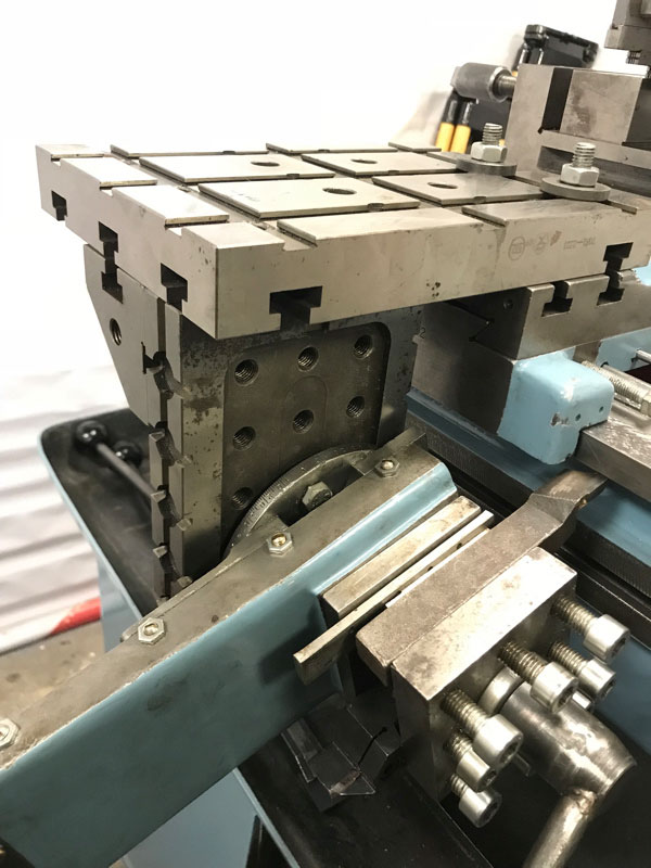
Fig.2
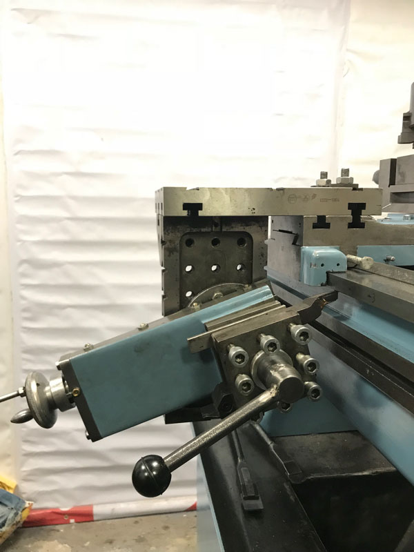
Fig.3
The device Fig.1, Fig.2, Fig.3 consists of two plates of USP assembled with each other, using corners. The top plate is fixed to the cross feed carriage. A small longitudinal feed with a tool holder is screwed to the lower plate. A small longitudinal feed serves to move the cutter vertically and is fixed at an angle to the horizon of about 6 degrees. The value of 6 degrees is chosen for the reason of a 10-fold decrease in the real displacement of the tool vertically. Thus, if for one division of the limb of a small longitudinal feed the displacement of the cutter is 0.05 mm, then vertically it will move to H = sin60x0.05mm, which is 5 microns. In fact, such small values should not be sought, it is enough to reduce by 2-5 times, which corresponds to the angles of 12-30 degrees. As can be seen in the figure, the author of the small longitudinal feed was screwed at an angle of about 30 degrees, which gave a vertical displacement of about 0.01 mm per division of the limb. The tool is moved horizontally by a transverse feed. The lathe chuck in Fig. 1 serves as a counterweight. The idea of this design is to use the already repaired parts of the machine itself. The use of USP slabs made it possible to exclude the manufacture of any additional assemblies and parts.
Operation.
Before the device is mounted on the machine, it is necessary to make measurements of the lower planes. This will allow you to determine the location on the bed in which you need to set the cutter to the initial height position. Cutter is installed by turning the toolholder.
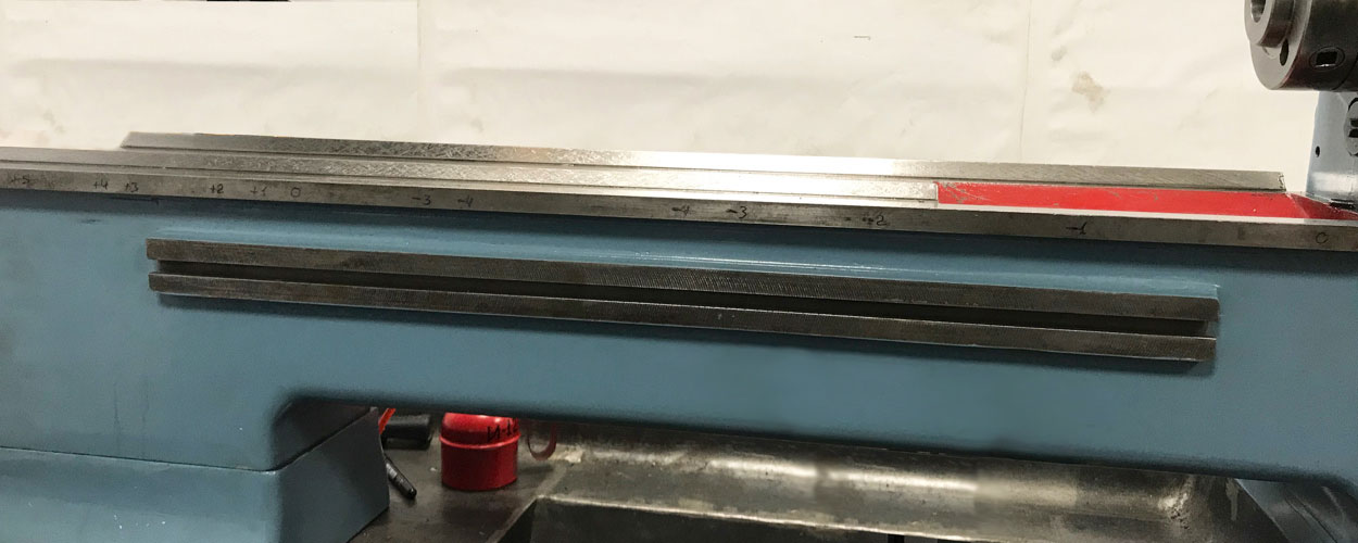
Fig.4
As can be seen from Fig. 4, the difference between the largest and smallest deviations reaches 0.1 mm. The figures correspond to a deviation of one hundredth of a millimeter. The plus sign corresponds to the downward deviation, the minus sign is up. The direction of planing from the center to the periphery (in this case to the front headstock). Cutter, in height, set at zero mark. I hope that readers imagine the process of planing, and I will not dwell on it in detail. I will only say that the optimal value of vertical feed is 0.01-0.02 mm, and horizontal - 0.1 mm per pass. The carriage with the device is driven manually.
The design does not allow the whole plane to be scraped from one installation and requires adjustment of the device. This does not require much effort, I note only that planing the second half of the plane requires the use of another cutter. In this case, the author used a pass-through left-handed and a pass-through stubborn right cutters.

Fig.5

Fig.6
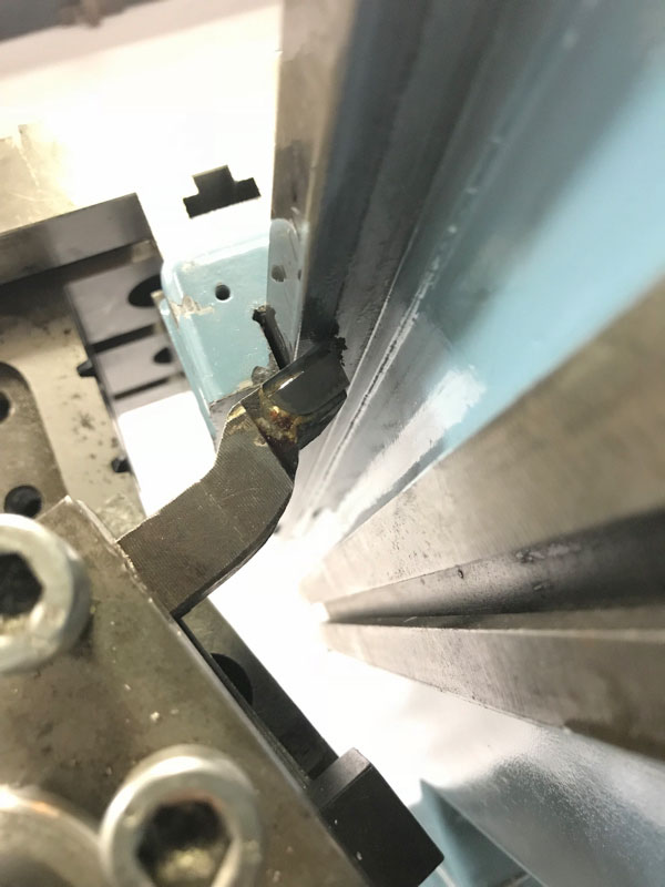
Fig.7
Figures 5, 6 and 7 illustrate the adaptation from different angles. Figures 8 and 9 show the adaptation after the readjustment for planing the second plane from the side of the prismatic guide. Since, from the side of the flat guide was repaired and installed a clamping bar, the need for a counterweight has disappeared.
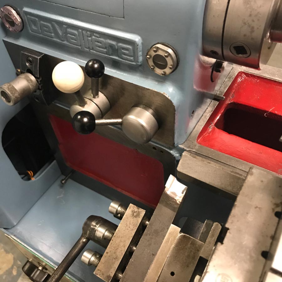
Fig.8

Fig.9
Features.
Conclusion.
With the help of the described device, the author managed to repair the lower planes of the bed ways with high accuracy, that is, the nonparallelism of the lower planes to the direction of movement of the support was 0.01 mm along the entire length of the bed. The result is more than satisfactory. The obtained results allow us to recommend this method to the use for repair of the bed of lathe-screw-cutting machines.
A bibliography.
- "Ремонт направляющих станин, столов и суппортов." Диафильм в 3 частях. Автор И. С. Стерин. Консультант кандидат технических наук Н. И. Думченко. Художник В. В. Петров. Редактор И. Н. Иванова. Издано фабрикой экранных учебно-наглядных пособий ..., Ленинград, 198095, ул. Зои Космодемьянской, 26, 1973г.