")
")
")

More precisely, a universal test bar. How it's made and how to use ...
With this article, I begin a series of materials on how to use various tools and tools in measuring linear dimensions, as well as deviations from a given value. I will try in simple language to describe how to use what and where to measure and what to look for.
Overview
Cylindrical test bars are cylinders of different diameters and lengths. All bars can be divided into two large classes - they are cantilever test bars and center test bars. Center test bars are ground hardened cylinders with two center holes in the ends. Are intended for installation in the centers of the machine tool and alignment on them of mutual displacements of units and units. For example, for such a test bar, it is easy to set the center of the tailstock of a lathe without resorting to a trial turning. You can check the straightness of moving the slide. You can set the table of the circular grinding machine to a given angle or vice versa to set the angle to zero. That is, the center test bars can be used where there are two centers (for fixing the workpiece as a rule). This somewhat reduces their scope.
Console test bars are more interesting and in demand. They represent a cylinder on one side of which an instrumental taper is made for installation in the machine spindle. The taper may be different. It can be a Morse taper, it can be 7:24, it can be a metric taper, a taper 1:50, 1:30, 1:10, etc. In the secondary market, there are many designs, lengths and diameters. Why do we need test bars ? First, for control. During operation, the wear of the guide machines is natural. This wear is not uniform, which leads to a violation of the geometric shape of the workpiece. The deviation of the movement of the support (table or other part of the machine) relative to the axis of rotation of the spindle will be controlled by the control frame. Secondly, during repair, it is often necessary to reconcile the relative position of the nodes relative to the axis of rotation of the spindle or the spindle itself (with its axis of rotation) relative to the movement of the machine components. The simplest example is the alignment of the headstock of the lathe with respect to the direction of motion of the support.
But, what if the tool taper requires repair from a spindle or is there no taper at all? That's where the universal test bar comes in handy.
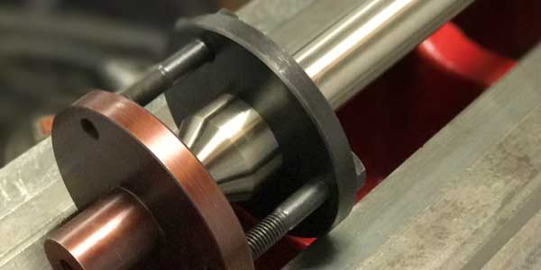
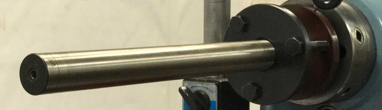
Fig.1

Fig.2
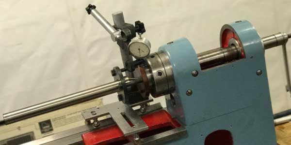
Fig.3
In the photographs, you can see the test bar in assembled form (Fig. 1), disassembled (Fig.2) and the assembled test bar is secured with a ramrod on the spindle of the headstock of the lathe (Fig. 3). As it seems to me, explanations to the photos are not required.
Tuning
The universal test bar needs to be preset. It means reconciliation and adjustment. For measurements during the installation, I recommend using a gauge with a scale division of 0.01 mm.. More accurate indicators are not needed. They do not help but on the contrary make it difficult to correctly align the test bar. It must be said that the accuracy of manufacturing (namely, the radial runout of the test bar and the flange), as a rule, is within 0.001-0.003 mm. The test bar is verified with an accuracy of 0.01 mm.

Fig.4
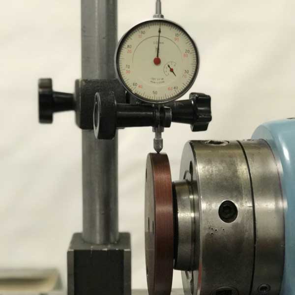
Fig.5
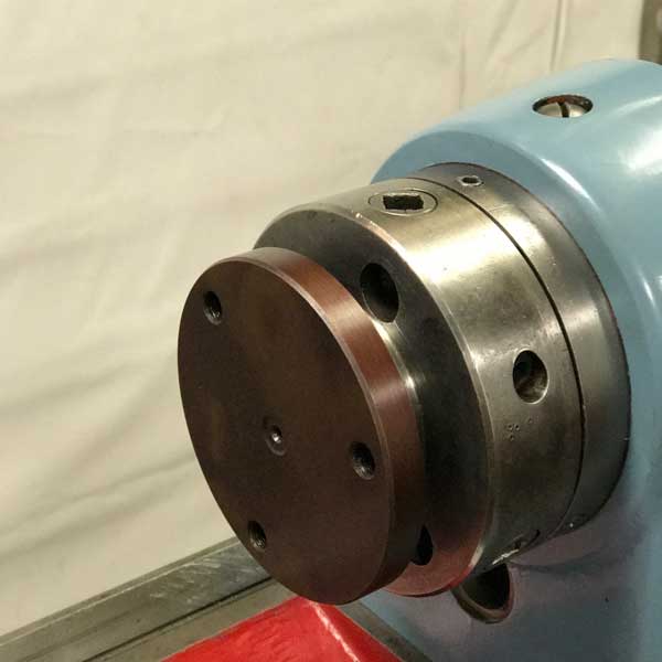
Fig.6
To begin with, the flange, with a centered hole (Fig. 4), is attached to the spindle. In this example I fixed it with a ramrod (Fig. 6). Then the flange is adjusted so that when the spindle rotates, the radial runout is minimal (Fig. 5). In practice, if for one turn of the spindle the arrow of the indicator deviates within one division (0.01mm), then the reconciliation can be considered finished. After aligning the flange, you must tighten the ramrod. If the spindle does not have a through hole, use another flange (Fig. 7, included in the kit). It is fixed from the drop on the spindle nut and washer. Check the flange for the indicator is not necessary.
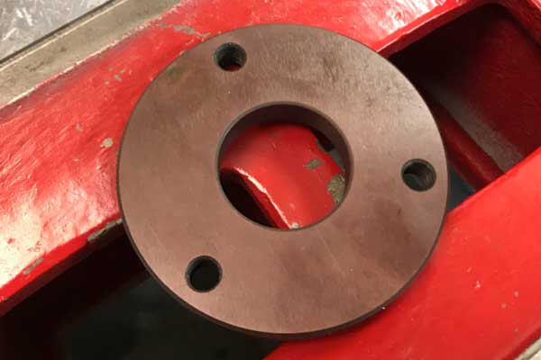
Fig.7
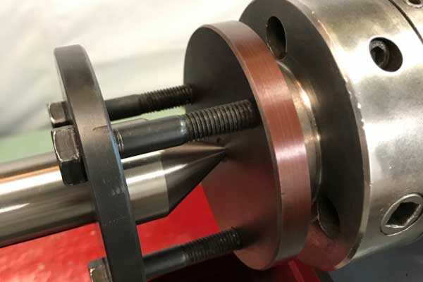
Fig.8
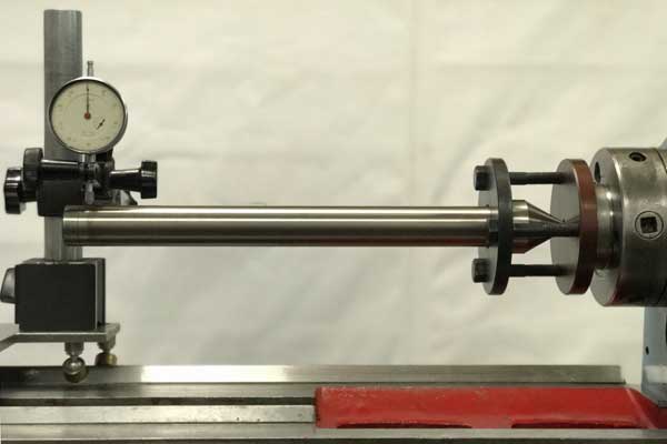
Fig.9
Then the point of the test bar is inserted into the center of the flange (or into the center hole of the spindle, if another flange is used) and fastened with a flange and three bolts (Fig. 8). Alternately pulling or releasing (if necessary) the bolts achieve a minimum beat at the end of the test bar (Fig. 9). Bolts should be tightened so much that the mandrel does not play. Shake the free end of the mandrel upwards with a little effort (aprox. 5-10N) and watch the indicator. After removing the force, the test bar must return to its place.
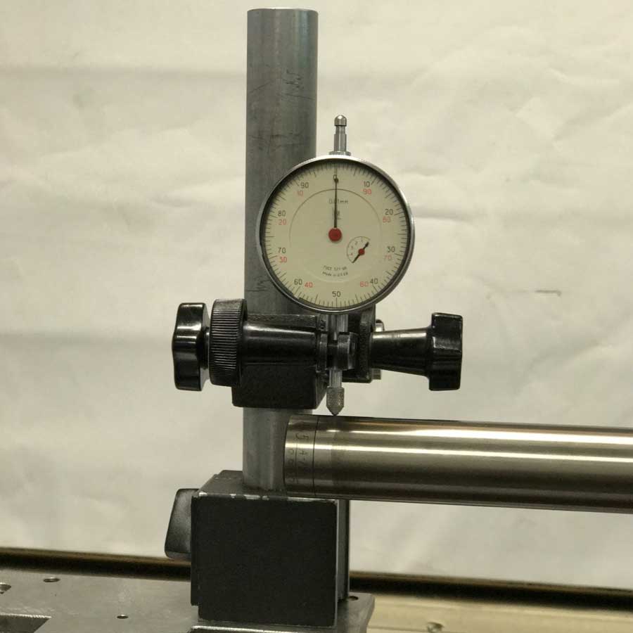
Fig.10
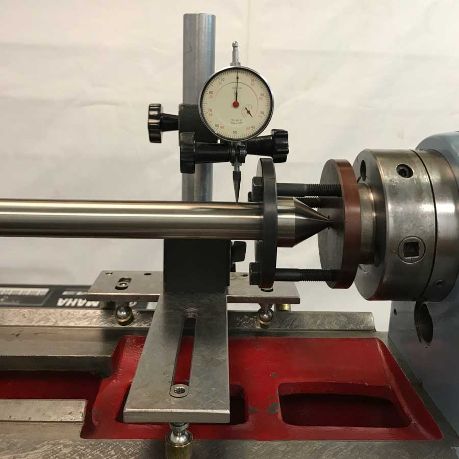
Fig.11
And further, it is necessary to check the beat of the test bar itself near the spindle. Despite the fact that in the example the flange was exposed almost to zero, the beating at the end of the mandrel was also close to zero, the beat near the spindle was 0.02 mm. If, however, the more sharp the test bar is inserted into the center hole of the spindle, then the runout will correspond to the spindle runout. In either case, the final operation will be to obtain a deviation of the free end of the test bar equal to the deflection near the spindle (Fig. 10, Fig. 11). Simply put, the test bar should deviate in the same direction by the same amount at both ends of the test bar. On this, the setting of the test bar can be considered complete.
A bibliography.
- "Технология ремонта металлорежущих станков." Пекелис Г.Д., Гельберг Б.Т. - Ленинград, "Машиностроение", 1970г.
- "Станки металлорежущие. Общие требования к испытаниям на точность." - ГОСТ8-82, 1982г.
- "Станки металлорежущие. Схемы и способы измерений геометрических параметров." - ГОСТ 22267-76, 1976г.
- "Испытания станков. Часть 1. Методы измерения геометрических параметров." - ГОСТ Р ИСО 230-1-2010, 2010г.