")
")
")

Print on the envelope or how to print the picture on the cylinder.
Suppose you have a machine for printing images using tampon printing. You successfully spank the advertisements on lighters, pens, and other souvenir products. But then the customer comes and wants his logo (or advertising slogan) to be printed on, suppose a round Chinese flashlight, not along and along the circumference. Like the inscriptions on the bank with sprats. Turn the flashlight around its axis and read.
That's great, is not it? Well, and how here to be? For these purposes, the tool described in this article is intended. I must say that the customer had a similar device. But it was small in size. The task, initially, was to be repeated on a larger scale. Structurally, the prototype was a slightly different solution. Longitudinal movement occurred on one shaft to the left, and on the right the carriage on the bearing on the base went. Transverse movement of the movable column took place along two guide shafts with a diameter of 4 mm. Everything worked fine, everything was fine. But here, as they say, size matters. When I tried to repeat the design on a larger scale, one unpleasant feature was discovered. The movable stand in the middle of the transverse stroke, which is called, began to play, tilt like a pendulum in the plane perpendicular to the guide shafts. Themselves, the shafts bent in an arc. There was a catastrophic loss of rigidity. Moreover, the diameter of the shafts was increased to 6 mm. In the extreme left and extreme right position, this effect was not observed. Further increase in the diameter of the shafts was impossible due to the requirement to provide a working space for the workpiece to be fixed. Dee and, to be honest, I'm not sure that it helped, so much was lost stiffness. It was a dead end.
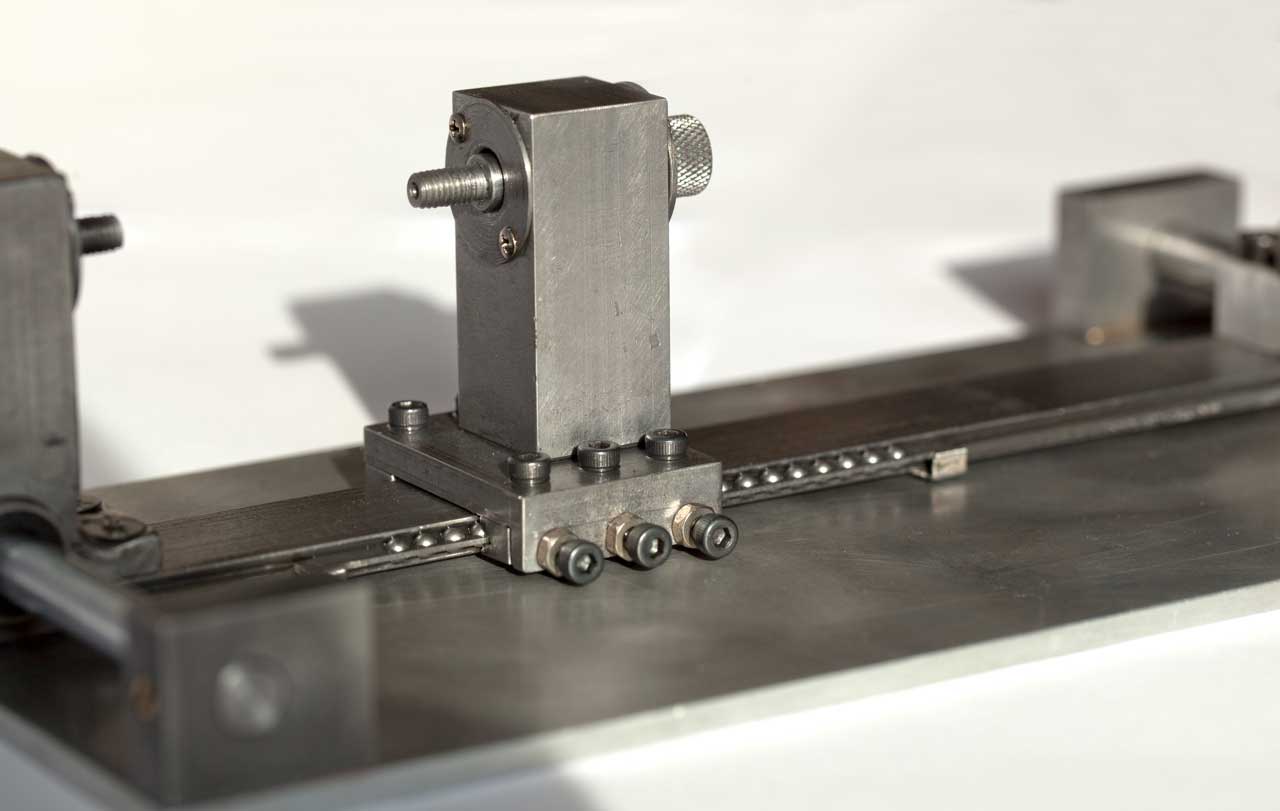
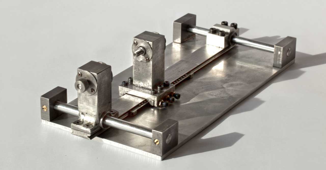
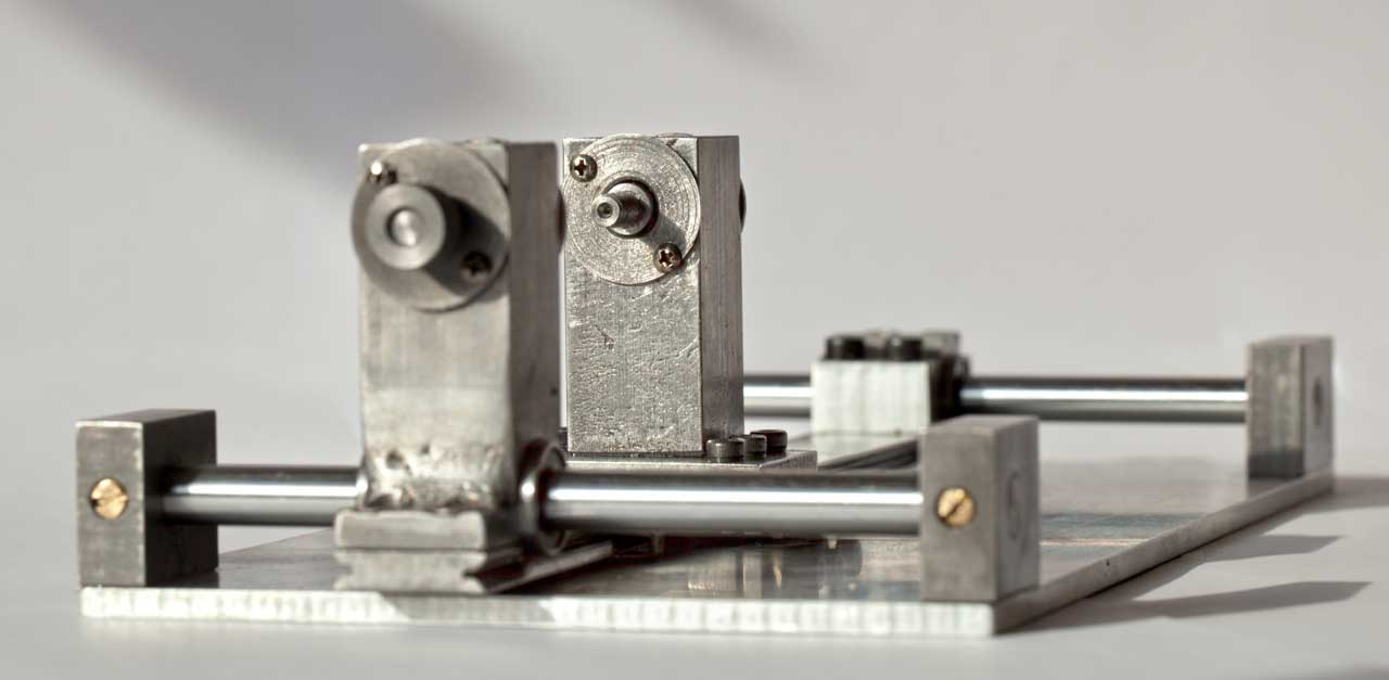
Then I proposed to change the design. In the end, it turned out the product you see in the photo. A radical change was the use of two (instead of one) shafts for longitudinal carriage movement and two linear bearings. The second radical design change was the rejection of two circular guides and the use of one flat rail for lateral movement of the movable post. To make the design low expensive, I made rail, separator and carriage, by myself.